Using the XML Destination Component
The XML Destination Component is an SSIS destination component used to merge input data based on the XML data structure defined in the component. You can then specify the component to write the merged XML document to a local file or you can send it to an HTTP URL to perform an XML or SOAP-based service call.
General Page
The General page determines what will happen with merged XML documents. The connection manager property can either be set to an HTTP Connection Manager which is used to send the document as part of an HTTP request, or a local file which is used to output the merged XML to a file.
- Connection: Local File
-
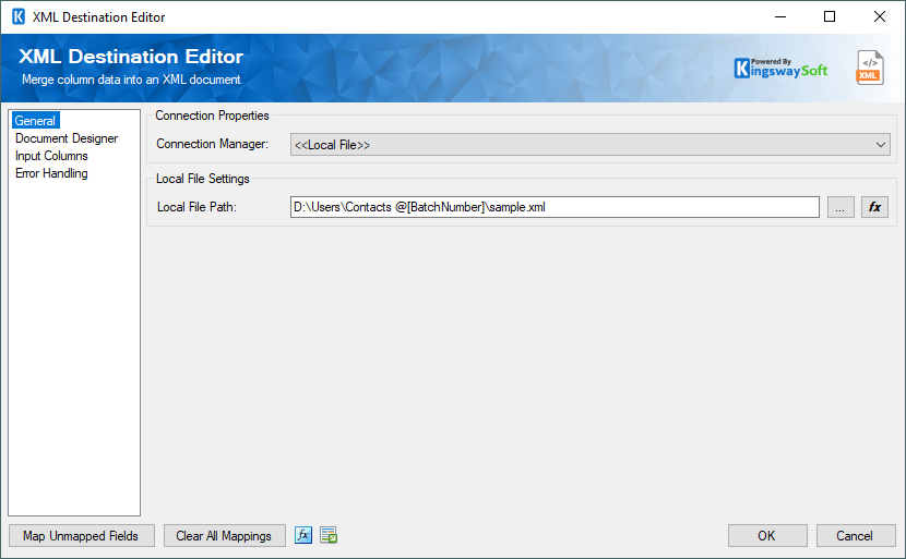
- Local File Path: The path on the file system where the XML document will be saved.
- Connection: HTTP Connection Manager
-
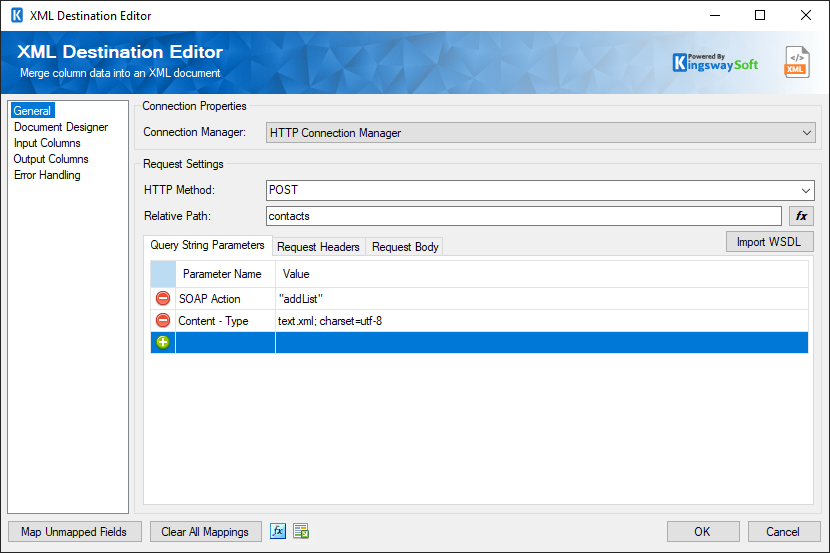
If an HTTP connection manager is selected the UI will display request settings that are used to determine the content of HTTP requests.
- HTTP Method
-
The HTTP method that will be used to send requests.
- Relative Path
-
The relative path is the second part of the URL that will be used to make the HTTP request. It is combined with the base path from the connection manager to form the full path. The relative path can contain query string parameters, but they can also be added individually in the grid below.
- Query String Parameters
-
Query string parameters that will be appended to the full path when sending HTTP requests.
- Request Headers
-
Request headers that will be combined with the headers in the connection manager and included with HTTP requests.
- Request Body
-
The body of the HTTP request.
- Import WSDL
-
Since v7.0, the XML Destination component supports importing WSDL to generate SOAP requests. Clicking the Import WSDL to load the WSDL file and build your SOAP request.
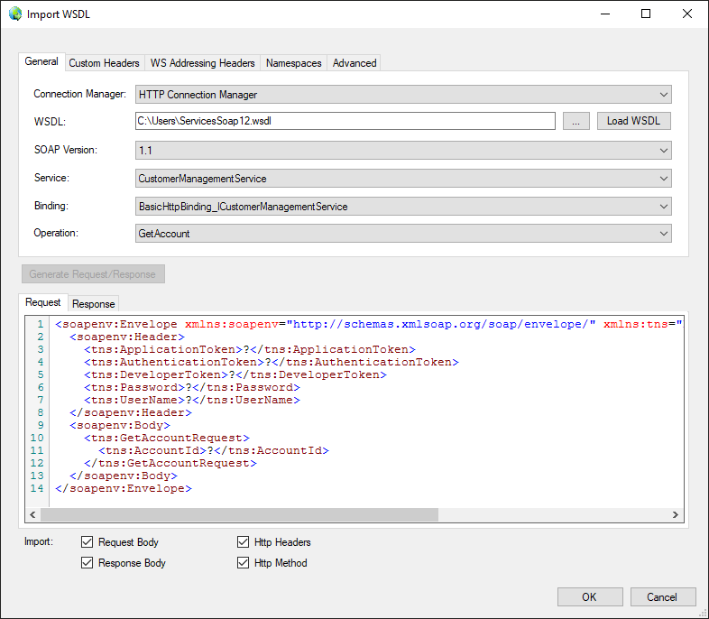
- WSDL
-
The WSDL specifies the location of the WSDL that you are trying to read from. This location can be either a location on the file system or a URL. For example, a value of c:\wsdl\mathservice.wsdl or http://localhost:28854/MathService.svc?wsdl will both work. There is a button labeled "..." beside the source WSDL field that will launch a dialog and let you select a file from the file system. If you select a WSDL file using the open file dialog provided by the "..." button the WSDL file will automatically be loaded upon clicking OK.
- Load WSDL
-
The Load WSDL button will try to load a WSDL file from the location specified in the Source WSDL field, and it will populate the other fields in the editor with information from the loaded WSDL file. Use this button after you have entered the path of a WSDL file into the source WSDL field. If you select a WSDL file from the open file dialog provided by the "..." button the WSDL file will automatically be loaded upon clicking OK.
- SOAP Version
-
The SOAP Version option indicates the SOAP version that the target web service uses. Our component will automatically detect the SOAP version while loading the WSDL file.
- Service
-
Select a Service from the list of services contained in the web service.
- Binding
-
Select a Binding from the list of bindings contained in the service.
- Operation
-
Select an Operation from the list of operations contained in the binding.
- Custom Header
-
Custom headers can be specified in the Custom Headers grid.
- WS Addressing Headers
-
WS-Addressing Headers can be used to specify message routing data within the SOAP request header per the target web service requirements. The following options are available:
- Unique Message ID (MessageID)
- Message Destination (To): Message destination URI.
- Source Endpoint (From): Source endpoint that dispatched this message
- Reply Endpoint (ReplyTo): Reply endpoint to which reply messages should be dispatched
- Fault Endpoint (FaultTo): Fault endpoint to which fault messages should be dispatched
- Action (Action): Required action.
- Relationship (RelatesTo): Message ID to which the message relates
- Namespaces
-
A namespace can be specified in the Namespaces grid.
- Generate Request Tree button
-
The Generate Request Tree button allows you to populate the SOAP request based on the latest changes you have made in the above settings.
- Request Tree
-
The Request Tree subgrid determines how input columns will be used to create the SOAP request.
- Expression fx icon
-
Click the blue fx icon to launch SSIS Expression Editor to enable dynamic updates of the property at run time.
- Generate Documentation Button
-
Click the Generate Documentation icon to generate a Word document that describes the component's metadata including relevant mapping, and so on.
- Expression Editor
-
Many of the properties on this page can be set as either a text-merged field or an expression. Properties default to text merge mode, but can be changed to expression mode in the Expression Editor. The expression editor for a property can be launched by clicking the fx button.
The expression editor has some predefined tokens:
-
- AccessToken
-
Returns the access token for sending requests. The token file needs to be generated by OAuth 2 Token Generated and specified in the HTTP Connection Manager's Authentication page.
- BatchNumber
-
The number of the batch that is about to be sent. On the first request, it will have a value of 1.
- MergedXML
-
This is the merged document that was created for the current batch.
- CurrentItem
-
This token is only available in the item key field on the output columns page. It represents an item in the array of response items.
- Text Merge Mode
-
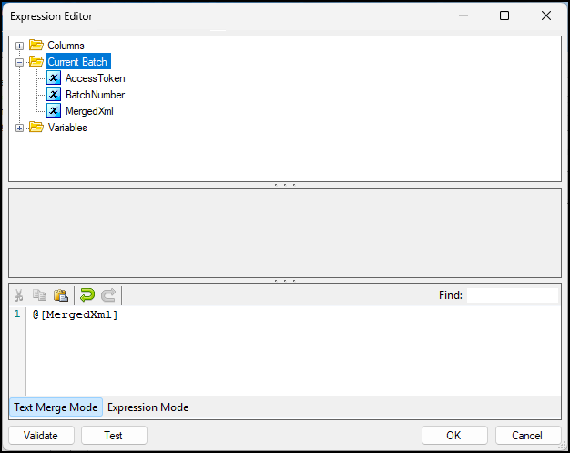
In text merge mode, property values will be whatever text was entered, but with any variables or special tokens replaced with their actual values before each HTTP request is sent.
- Expression Mode
-
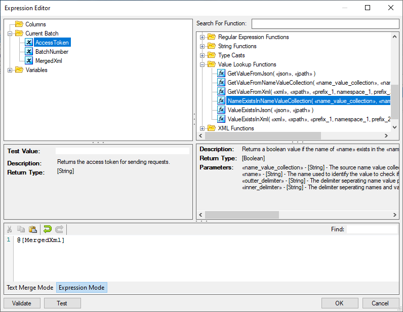
In expression mode, the property is set to an expression which is evaluated before each request to determine the value of the field. Expressions can contain variables and special tokens, but also functions and conditional logic. The functions in the Value Lookup Functions category may be particularly useful for this component, as they can be used to look up values and XML documents and HTTP headers.
-
Document Designer Page
The Document Designer page allows you to build the design of the document you are trying to write to, or import the design from an existing document.
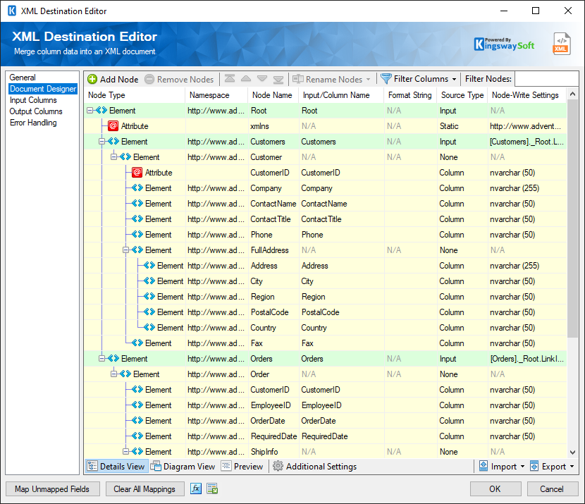
The Document Designer includes the following four tabs:
- Details View.
- Diagram View.
- Preview.
- Additional Settings.
In the Details View tab, the top part of the page is used to manually configure the nodes in the design:
- Add Node: This button will add a new node to your Document design.
- Remove Nodes: This button will remove a node from your Document design.
- Direction buttons: These buttons can be used to rearrange the position of the nodes.
- Rename Nodes: This option allows you to specify how the node name should be represented.
-
- Use Qualified Names: When this option is selected, the output/column name will be set to the full qualified node name based on the node location in the document.
- Use Short Names: When this option is selected, the output/column name will be set to the given Node Name directly.
-
Filter Columns: This option allows you to show or hide certain Columns in the grid.
- Show Basic Columns: When this option is selected, only basic columns will be shown in the grid.
- Show All Columns: When this option is selected, all available columns will be shown in the grid.
- Filter Nodes: This option allows you to filter the list of nodes shown in the grid by typing a keyword in the textbox.
The Details View grid consists of:
-
Node Type: This option allows specify the type of the Node in your document design. There are three options available:
- Element
- Attribute
- Raw: This type can be used when trying to write data under a node exactly as it is from an upstream pipeline component.
- Namespace: This option allows you to specify the Namespace to which a node belongs (Available when Show All Columns is selected).
- Node Name: The Name of the Node in the document.
- Input/Column Name: The name which will be used for the node when writing to the document.
- Is Repeated: This option allows you to specify if a node is repeated within a document (Available when Show All Columns is selected).
- Format String: This option allows you to specify the target output format for a string when converting datetime/number values to a string. It follows the same .Net formatting function found at this link. (Available when Show All Columns is selected)
- Source type: The type of the input for a node such as a dedicated Input, Variable, or Column, depending on the Node Type.
- Node-Write Settings: This option allows you to specify the settings of each node such as the datatype or the Variable Name based on the selected Source Type.
-
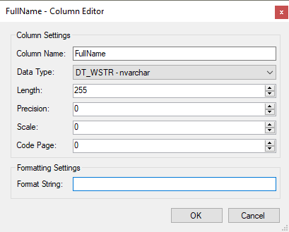
- Column Name: The name of the column.
- Data Type: The data type of the field which can be changed accordingly.
- Length: This option allows you to specify the Length of the fields. If the data type specified is a string, the length specified here would be the maximum size. If the data type is not a string, the length will be ignored.
- Precision: This option allows you to specify the number of digits in a number.
- Scale: This option allows you to specify the number of digits to the right of the decimal point in a number.
- Code Page: This option allows you to specify the Code Page of the field.
- Format String: This option allows you to specify the target output format for a string when converting datetime/number values to a string. It follows the same .Net formatting function found at this link.
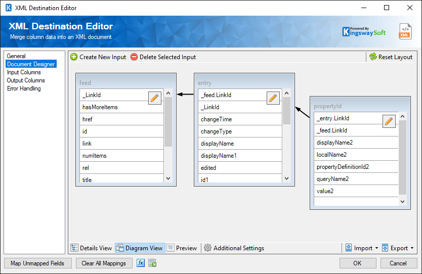
In the Diagram View tab, you would be able to view the document design as a diagram where you can link different inputs with each other in order to create the hierarchy of your document and establish relationships between the different inputs:
-
- Create New Input
-
This option allows you to create a new Input and link it to an existing input if required based on the intended document design.
- Delete Selected Input
-
This option allows you to remove existing Inputs from the diagram
- Reset Layout
-
This option allows you to reset the layout of the diagram which would reorganize the location of each input.
In the Preview tab, the component will show a sample of the document which will be created with test values.
In the Additional Settings tab, you would find the following options:
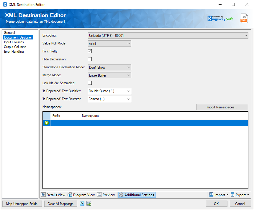
- Encoding: The encoding of the document that will be written.
-
Null Mode: This option allows you to specify the handling of Null values. There options available are:
- Don't Show
- Empty String
- xsi:nil
- Print Pretty: When true, the merged XML will contain line breaks and indents. When false, the merged XML will be a single line of text.
- Link Ids are scrambled(since v23.1): This option becomes relevant when there are multiple inputs available for the merge or writing. The option specifies whether those Link Ids are scrambled between the inputs. When the option is checked, it indicates that Link Ids can come from the source system in random orders, in which case our software will perform an in-memory matching and joining, which could substantially impact the merge/writing performance. If the incoming Link Ids are not scrambled (for instance, those Ids are properly sorted in an ascending order within each input), this option can be unchecked, which will emit some much greater merge/writing performance, and it could also avoid out-of-memory exceptions when working with a large data set if disabled.
- Hide Declaration: Specifies whether or not the merged XML should contain the XML Declaration line.
-
Standalone Declaration Mode: An attribute in the XML Declaration, available if Hide Declaration is unchecked.
- Don't Show: When the ML document does not include a standalone declaration.
- Yes: Declare the XML document as standalone, it does not rely on external document type definition for structure or default values.
- No: Declare the XML document is not standalone to indicate document type definition are required to interpret the document.
-
Merge Mode: Input rows can be batched and sent in a single request. There are 3 batch modes:
- Every Row: This mode is like a batch size of 1. A single file will be created using the merged XML from each input row.
- Every Batch: This mode lets you specify the batch size. Some number of files will be created, each containing the merged XML from the number of rows specified in the batch size property.
- Entire Buffer: This mode is like an unlimited batch size. Only one file will be created, and it will contain the merged XML from all the input rows.
- Batch Size: When the 'Every Batch' Merge mode is selected, the Batch Size can be specified.
-
'Is Repeated' Text Qualifier: This option allows you to specify the
Text Qualifier used in a document when the
Is Repeated property is set to
True for one or more nodes. There are four options available:
- Double-quote(“)
- Single-quote (‘)
- Tick (`)
- None
-
'Is Repeated' Text Delimiter: This option allows you to specify the
Text
Delimiter used in a document when the
Is Repeated property is set to
True for one or more nodes. There are seven options available:
- Newline (\n)
- Carriage Return (\r)
- Semicolon (;)
- Colon (:)
- Comma (,)
- Tab (\t)
- Vertical Bar (|)
- Namespaces: Add and remove namespaces (by clicking the '+' and '-' buttons) and assign them prefixes. Note, the prefix does not need to match that of the incoming XML. It is simply used as an alias in XPaths that use this namespace.
- Import Namespaces...: Import Namespaces that are defined in an XML file on your local file system.
- Import
-
This option allows you to import the design of your document from one of the following sources:
- Designer Settings: Import the design from an existing .designer.settings file.
- Input (Reset Design): Create the design based on the input columns for the upstream components.
- WSDL (Local File): Import the design based on a WSDL file on your local file system.
- XML (Local File): Import the design based on an XML file on your local file system.
- XSD (Local File): Import the design based on an XML Schema file on your local file system.
- Export
-
Designer Settings: This option allows you to export the current document design to a .designer.settings file which can be used later to import the same design in a different component.
Input Columns Page
The Input Columns page of the XML Destination Component allows you to map the columns from upstream components to the defined nodes for the designed document.
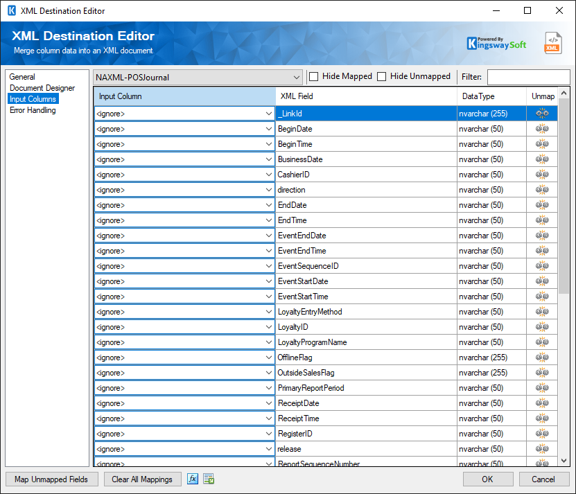
- Input Column: Select an Input Column from an upstream component.
- XML Field: This is the field you are writing data to
- Data Type: This column indicates the type of value for the current field.
- Unmap: This column can be used to unmap the field from the upstream input column, or otherwise it can be used to map the field to an upstream input column by matching its name if the field is not currently mapped.
Output Columns Page
Output Columns can be configured on this page. The values of output columns will be extracted from the response of any HTTP requests that are sent. Output columns are typically used to get success or Id information about items that were created/updated or deleted on the server.
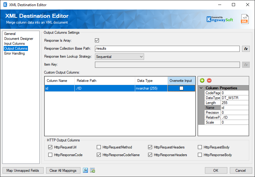
- Response Is Array
-
Check this property if the HTTP response will contain an array with items corresponding to your input rows. If the response does not contain information about each input item you wouldn't need to check this property.
- Response Collection Base Path
-
If your response contains an array, the response collection base path property will be the XPath that will return the items in the array.
- Response Item Lookup Strategy
-
If your response is an array a strategy must be selected to match input rows to response array items.
- Sequential Strategy: If this strategy is selected it is assumed there are an equal number of input rows and output array items, and they are matched in the order they appear.
- Item Key strategy: Use this strategy when the output array items are not in the same order as the input rows. Selecting this strategy will allow you to define an item key below which will determine how input rows are matched to output array items.
- Item Key
-
If the item lookup strategy is used an item key expression must be defined. This expression will be evaluated for each input row in the batch and each array item in the response and should return true for a match and false when they are not a match. The CurrentItem token is available in the expression editor and will allow a value from an array item to be easily compared to a column value to match rows and response array items.
- Output Columns Grid
-
The output columns grid contains any output columns. Output column values will always come from the HTTP response. If the response is not an array the relative path should be the full XPath to the output value in the HTTP response. If the response is an array the relative path will return the value at the specified XPath for the response array item that has been matched to the current output row.
The Output Columns grid consists of:
- Column Name: Name of the column that will be outputted in the Default Output.
- Relative Path: Specify the XPath of the output value in the HTTP response.
- Data Type: The data type of this field.
- Overwrite Input: Indicate if the input column will be overwritten.
-
Column Properties: Properties window for the field listed. These values are configurable.
- CodePage: Specify the Code Page of the field.
- DataType: The data type can be changed according.
- Length: If the data type specified is a string, the length specified here would be the maximum size. If the data type is not a string, the length will be ignored.
- Name: Specify the Column name.
- Precision: Specify the number of digits in a number.
- Relative Path: Specify the XPath of the output value in the HTTP response.
- Scale: Specify the number of digits to the right of the decimal point in a number.
- +sign: Add columns to Output Column grid.
- - sign: Remove columns from the Output Column grid.
- HTTP Output Columns (since v9.0)
-
Checking or unchecking these columns will add or remove HTTP related additional output columns. The following columns are available:
- HttpRequestUrl: The URL of the request
- HttpRequestMethod: The HTTP method of the request
- HttpRequestHeaders: All of the HTTP headers of the request
- HttpRequestBody: The text body of the request
- HttpResponseCode: The HTTP status code of the response
- HttpResponseCodeName: The name of the HTTP status code of the response
- HttpResponseHeaders: All of the HTTP headers of the response
- HttpResponseBody: The text body of the response
Error Handling Page
The Error Handling page allows you to specify how errors should be handled when they happen along with the name of the output column that will contain the merged XML.
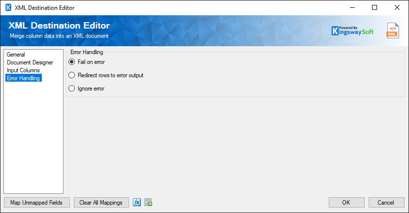
For Error Handling the below options are available.
- Fail on error
- Redirect rows to error output
- Ignore error
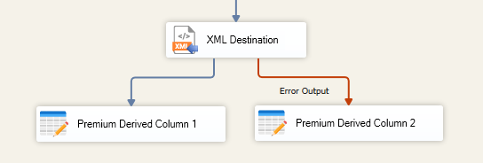
When the Redirect rows to error output option is selected, rows that failed to be sent will be redirected to the 'Error Output' output of the Transformation Component. As indicated in the screenshot below, the green output connection represents rows that were successfully sent, and the red 'Error Output' connection represents rows that were erroneous. The 'ErrorMessage' output column found in the 'Error Output' may contain the error message that was reported by the component.